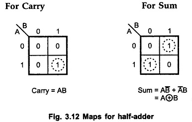

- #Half adder truth table and circut generator#
- #Half adder truth table and circut serial#
- #Half adder truth table and circut full#
HDL assignment statements ( assign in SystemVerilog and <= in VHDL) take place concurrently. Library IEEE use IEEE.STD_LOGIC_1164.all In VHDL, signals are used to represent internal variables whose values are defined by concurrent signal assignment statements such as p <= a xor b In SystemVerilog, internal signals are usually declared as logic.
#Half adder truth table and circut generator#
′0′ after 100 ns, ′1′ after 120 ns, ′0′ after 140 ns, ′1′ after 160 ns,Īrchitecture Behavior_desc of Test_bench isįor S 0: Generator use entity Test_gen(Behavior_desc) įor S 1: Adder use entity Full_Adder(Behavior_desc) īegin -Connect the ports of the components VHDL description of a test bench for the full-adderĪrchitecture Behavior_desc of Test_gen isĪ < = ′1′, ′0′ after 20 ns, ′0′ after 40 ns, ′0′ after 60 ns, ′0′ after 80 ns, ′1′ after 100 ns, The description is in terms of the previously defined components. A structural style is used in the architectural body for the full-adder. Next we declare the design entity Full_ Adder and its port map. The statement wait on X, Y suspends the logic process until at least one of the signals, X or Y, is changed. Note that there is a special assignment operator used to propagate signals (<=). Port(In 1 = > Temp_carry 1, In 2 = > Temp_carry 2, Out 1 = > Carry_out) įirst we declare the two entities Half_ Adder and OR_ gate and their architectural bodies in a behavioral style. Port(In 1, In 2: in Bit Out 1: out Bit) įor U 0: HA use entity Half_Adder(Behavior_desc) įor U 1: HA use entity Half_Adder(Behavior_desc) įor U 2: OG use entity OR_gate(Behavior_desc) īegin- Connect the ports of the components

Signal Temp_sum, Temp_carry 1, Temp_carry 2: Bit Port(A, B, Carry_in: in Bit Sum, Carry_out: out Bit) Port (In 1, In 2: in Bit Out 1: out Bit) Īrchitecture Behavior_desc of Half_Adder is VHDL description of a half-adder and a full-adder Additionally C o is clocked to the output of the flip-flop and becomes the next C in, while the sum of the two least significant digits is clocked into the left-hand end of R 1 This process is repeated on receipt of each clock pulse ( Ck1) until the two numbers stored initially in R 1 and R 2 have been added and the resulting sum has been clocked back into the register R 1 If at the termination of the addition C o = 1, this will represent the most significant digit of the sum. Ck1 is now used to shift right the digits in registers R 1 and R 2, thus presenting the next most significant pair of digits at terminals A and B. With M = 1, Ck2 is disabled and Ck1 is enabled.
#Half adder truth table and circut full#
The corresponding sum and carry-out appear at the output terminals of the full adder. With M = 0, Ck2 is enabled, the flip-flop is cleared, and the registers are loaded with the two numbers to be added so that the two least significant bits are available at terminals A and B. The selection of either of the two clock pulses is a function of the mode control M (see Figure 12.12).

The basic element of the circuit is a full adder which is operated in conjunction with a DFF and a pair of shift registers which have parallel loading and shift right facilities controlled by Ck1 and Ck2.
#Half adder truth table and circut serial#
Compare delay and size with a 2-bit carry-ripple adder implemented with (radix-2) full-adders (use average delays).Ī serial adder uses a sequential technique and may be regarded as a very simple finite state machine. 2.3ĭesign a radix-4 full adder using the CMOS family of gates shown in Table 2.4. L load on the gate output * different characteristics for each input + XNOR same characteristics as XOR for full-adder characteristics see Table 2.2 2.2ĭetermine the delay of a 32-bit adder using the full-adder characteristics of Table 2.4 (average delays).


 0 kommentar(er)
